Wiki
Sidebar
projects:maps:overview
☚ Instrumenten-Übersicht ★ ####################### ★ MAPS-2021 ★####################### ★ New MAPS-DAQ-Hardwareinfo ☛
The MAPS modernization is a long-term activity, yet unfinished.
Warning: the wiki pages below refer to an intermediate development step, which was never set into operation!!
For up-to-date information of the now restarted MAPS modernization project follow the link New MAPS info above!!
MAPS System Overview (INTERMEDIATE STEP!)
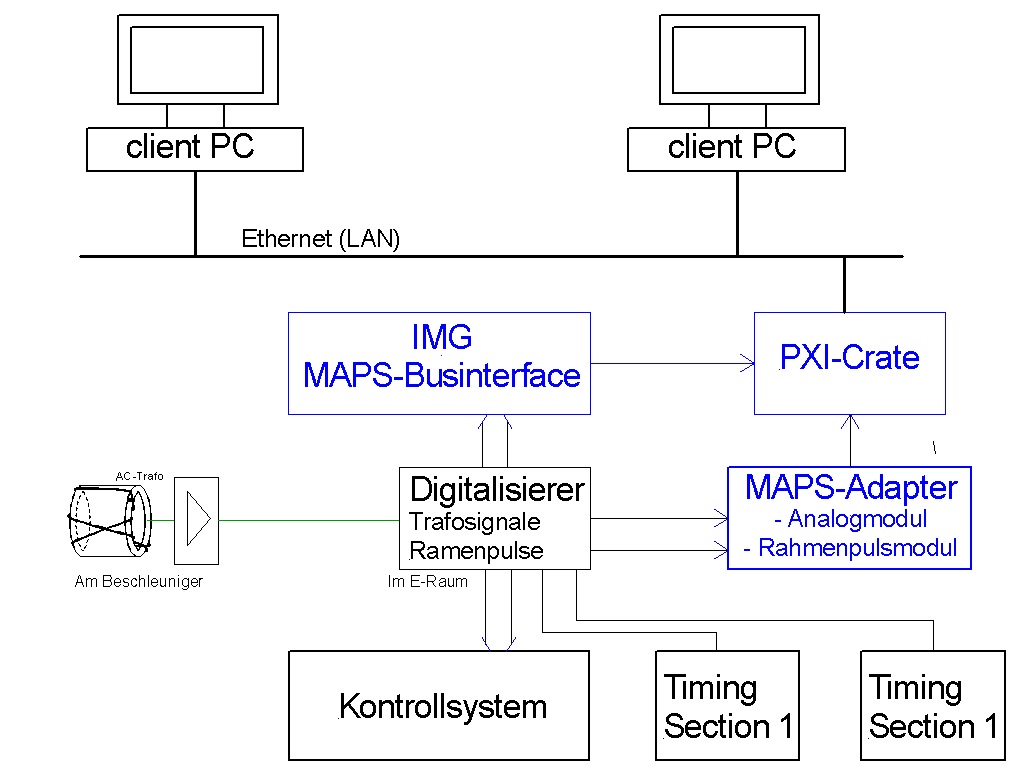 | Präsentation M. Laroussi Schwarz: MAPS-System in Kontrollsystem Blau: Neues MAPS-System BCT digitizer Trafos und Timing ☛ | 2005 —- Plan —→ 2012 |
The “MacroPulseSelector” system was built to display analog signals of UNILAC beam current transformers (BCT), as an addition to the already established beam current readout (for average macro-pulse currents) via the GSI control system. It utilizes a client-server architecture. The DAQ and server hardware run on a NI-PXI crate under LabView® RT. One or more users can choose two or more out of up to 128 BCT signals for the display by the client software. The project was initiated by A. Peters (former SD-group head) in 2005 and developped by M. Laroussi (diploma graduation work), Dr. H. Brandt (GSI EE, server software), M. Hartung (GSI SD, client software), and M. Kümmerling (Hörmann-IMG GmbH, MAPS interfaces, SerDes hardware, PXI interfaces) .
| Real physical layout inside 19“-rack | Description modules top down |
|---|---|
 ################################################### | 1.) Test-PC (Top of Rack) 2.) MAPS-Adapter consisting of ”Analogue signal module“ (6H below, half equipped) and ”Rahmenpulsmodul“ This adpter collects on it's rear panel: * up to 128 BNC analogue signals, feeding them via 8 NI multi-line-cables on the front to 8 NI ADC boards with eight channel each. * 8x Backside inputs LEMO 00 and 8x Monitor outputs on front for Timing signals to be fet to NI-ADCs: Here the saple window is given to the ADC: can be fet chooseable 1) to one of eight “Programmable Timing Inputs on board and backplane (PFI0..7). 3.) Rahmenpulsmodul: collects Timing signals from “Digitizers” moduls: This moduls sample Trafo signals for existing control system. Trafos Analog signals and Timing to that modul are then passed to additional new MAPS system 4.) NI-PXI Crate * Houses 8x ADC-boards for digitizing the analog signals and * 1x PXI7811 FPGA board to extract informations about beam properties (ACC no., gate pulse duration, status) from MAPS bus 5.) T-Test7811: Three modules in 19” frame: Only indroduced if signals between one of two signal sources if signals inside collecting cable are to be meassured. Pass out of signals for measuring purpose (Oszzi) 6.) MAPS-Bus-Interface: This is the modul in 3U 19” frame connected with the red cable: interface extracts informations of actual virtual accelarators from MAPS-bus to pass it to NI-crate 7.) Timing box creates general timing gate pulses (50 Hz start trigger, EOC) passed to leftmost adapter (front panel) in MAPS adapter. Shown modul is the receiver and of course there is although an sender to that. |
The actual sources of analog signals and gate pulses (“Rahmenpulse”) are the BCT digitizer modules.
Currently only half of the DAQ system is eatablished (64 from 128 possible BCT channels). The fully extented state is schematically shown here. 16 (grey) cables are equipped with 68-pin 0.050 D-Type connectors at both ends, and carry the analogue BCT signals to the ADC-boards. 4 black cables with VHDCI 68-pin male type connectors on the FPGA side and 68-pin 0.050 D-Type on the other end carry gate pulses (“Rahmenpulse”) to the FPGA board:

Diploma Thesis from Mohammed Laaroussi
☚ Instrumenten Übersicht ★ ##########################################★ New MAPS info ☛
1)
Hardare
projects/maps/overview.txt · Last modified: 2021/07/22 09:04 by carsten