Wiki
Sidebar
projects:maps:mapsadapter:rahmenpulsmodul:overview
Table of Contents
☚ Back ★
Rahmenpuls-Modul
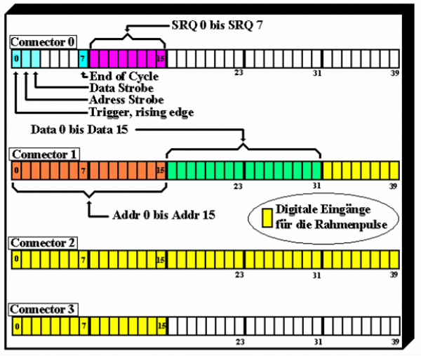
The realized signal flow through the for IO-connectors of PXI-7811R is:
This differs from the flow suggestion made in diploma theses from M. Larrousis, but is conncerted with programmers. Reason for that is to clear seperate yellow signals “Rahmenpulse” from the other signals. They chair the same target but come from different places. The opponent from connector 0/1 are now connected to the MAPS-Interface while the connectors opponents of connector 2/3 lead to the MAPS-Adapter.

Yellow inputs receive “Rahmenpulse” which maybe different for each of the up to 64 designated Transformators. That is due to the inhomogenus structur of timing zones in GSI. Frontside of the NI-FPGA Board splits the 160 Inputs of FPGA into four connectors. The related Ni cable combines two of those connectors each at one cable side to on 68 pin connector at the other side. Therefore one cable is directed to Rahmenpulsmodul and the other to MAPS-Interface to receive commands from users at distant client PCs: they choose four of maximal 64 trafos to be displayed. For those beam source and beam target information is received from MAPS-Bus. FPGA-programm shout manage information flow from bus and select the realated four timing inputs. They must be directed towards the related ADC boards out of eight to sample the trafo pulses if they arise. Pulses then are displayed together even they occure at the same time!
To get an impression see folowing Dokument for UNILAC-Timing zones (Thanks to C.Andre): UNILAC-Timing 2009.
The idaer shout be to combine all those AC-transformators inside the same time zone at same ADCs for being sampled from the same trigger!
Designated Diploma Signal Flow to NI-FPGA "NI87xx"
Old setup: Here the designated signal distribution does not face the two different signal sources which has to be reached which one cable each!
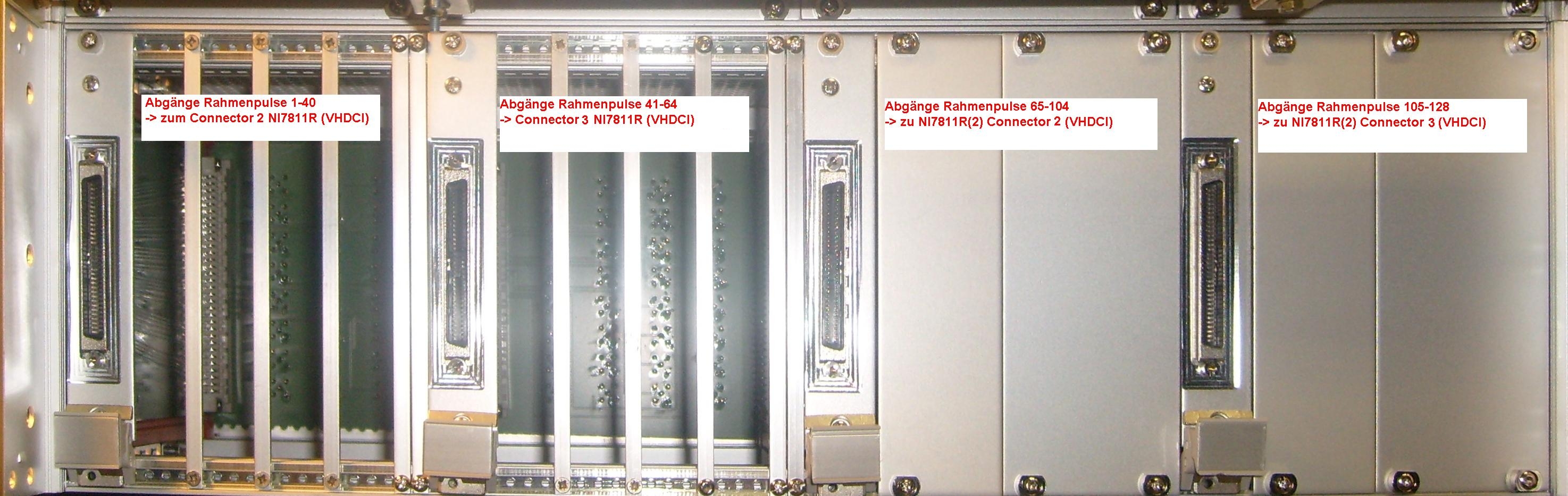
Physical Realization :
There are only 40 usable signal lines per cable
####
Boards
“Rahmenpuls” module houses two different kinds of boards:
Board "Rahmenplsback": collects Rahmenpulse from back of chassis.
Board AMP68VG96: adapts Rahmenpuls signals from backplane via VG-connectors to front connectors (68-pin 0.050 D-Type).
Internal pictures
Rahmenpulses are feet from rear panel via internal cables to the adapter “AMP68VG96”. The reason for having a cable indroduce instaed of going direct out is to keep away mechanical stress if cables on back are often channged.

Infos zu Trafos und Timing
projects/maps/mapsadapter/rahmenpulsmodul/overview.txt · Last modified: 2020/02/03 10:53 by carsten