Wiki
Sidebar
projects:maps:mapsadapter:analogsignalmodul:overview
Table of Contents
☚ Back ★
Internals Analog signal modul
0) Preamble
In existing MAPS system up to 64 transformer (ACT) signals are present (s. list here ☛), that should be later expandable to 128 channel all. To fetch a short puls signal at the right moment in time a trigger signal for has to be given. Due to different timing domains in principal for each of the 64 ACTs although 64 different triggers have to be applied. Infact and GSI-reality there are below 10 different timing domains in area of UNILAC where ACTs are at home.
NI-Carte shares eight common lines for real time triggers on backplane. Each single ADC modul can in principial receive such triggers via 68 pin front end connector. Those are connected with cable to 8 preseted adapeter cards in MAPS-adapter. This adapter cards collect analog signals for 8 ACTs and provide additional one external Lemm 00 port for i. e. feed in a external trigger. That could be used either only from the special connected single ADC or can be passed out to the backplane to be spread around to all other ADCs.
At UNILAC beam packages comes with a maximum rate of 50 Hz, which means a time intervall of maximum 20ms per puls. In fact beam puls is shorter from 5-6 ms and in the rest of intervall up to 20ms next beam target is configured. Because acclaration fastly leads to high flight speeds differences in arival times even between the first and the last ACT postion 150 m away is in range of a µs, what nearly can't be seen. Nevertheless oportunity of different triggers is given from hardware even if only one is required!
1.) Signal flow for ADC-gate (Trigger)
The following picture illustrates the flow of meassurement gate “Messfenster” from the input at one of the Lemo connectors at the front placed about the huge connector (alternativ on back side under analog BNC-inputs): Current default input is the most left module from front side. This signal can be directed on the “68AMP_9Lemo-board” via jumper to one of ten (PFI0-PFI9). Deault is PFI0. PFI-Lines to the connected NI-ADC PXI-6133. These are Programmable Funktion Inputs . They can be determed to be an input our an output. This will be done in the setup of the ADC-board. Inside the PXI-crate this signal is then distributed to all other ADC-bords. It might be possible to get it out again at 68AMP_9Lemo-board if the related board on the other ADCs ist determed to be an output then.

2.) Boards
This module does only house board Board "68AMP_9Lemo".
3.) Internal pictures
Grey comments are possible adptions to MAPS2020!
| Front | Back | |
|---|---|---|
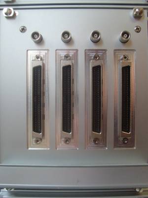 | 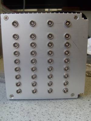 | Front and back of one of four submodules: Front: 4x board with each: 1x Front 68pol connector to NI-ADC (8 channel) ⇒ 2x RJ45 (4 channel) = Σ 8x RJ45 1x LEMO 00 monitor output ⇒ 4x trigger @ X2 connector Back: 1x LEMO 00 Timing input 8x LEMO 00 diff. analog input per trafo (internal) |
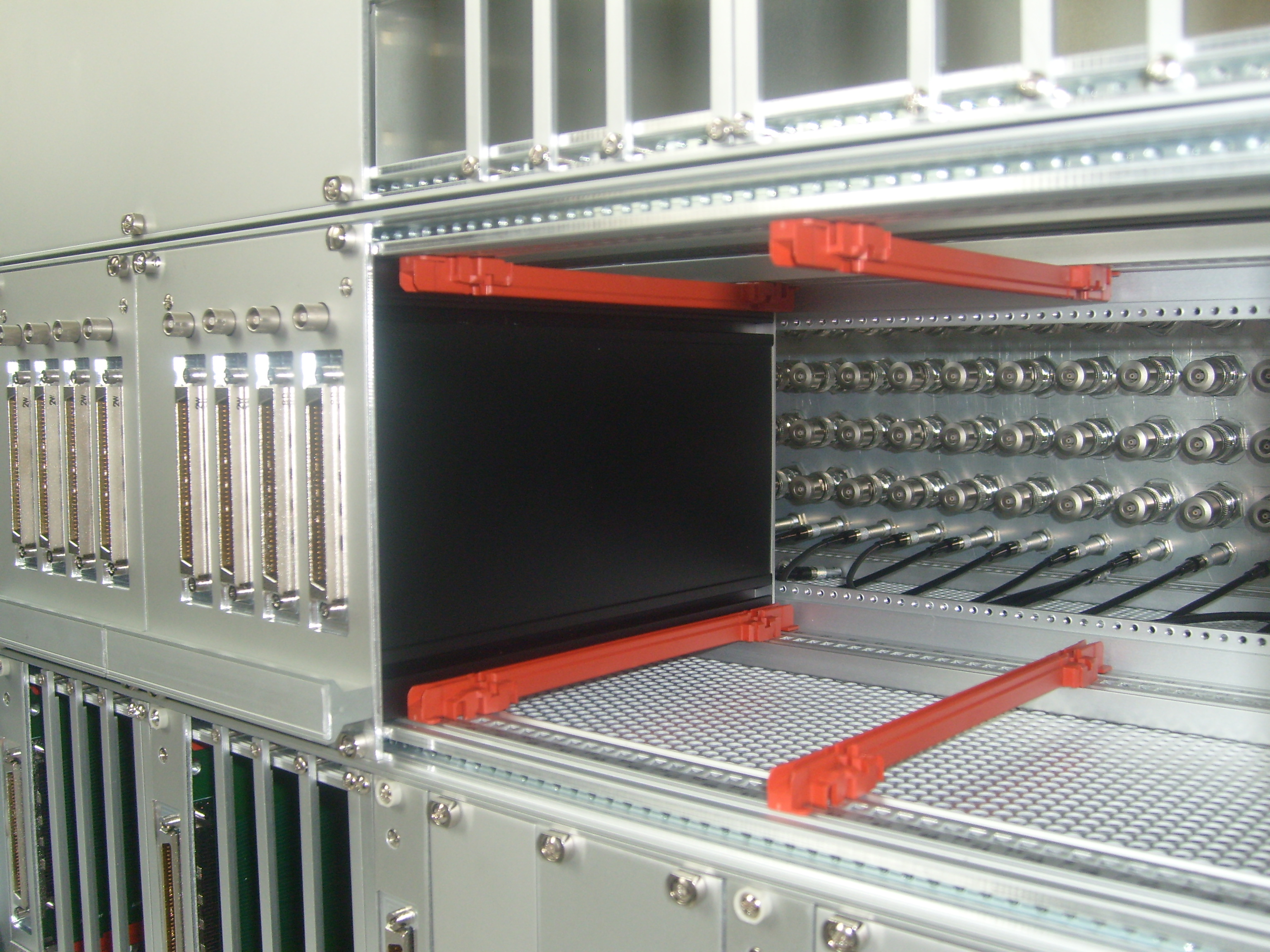 | View inside analog modul | |
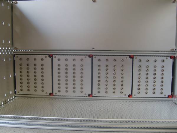 | modules internal back side | |
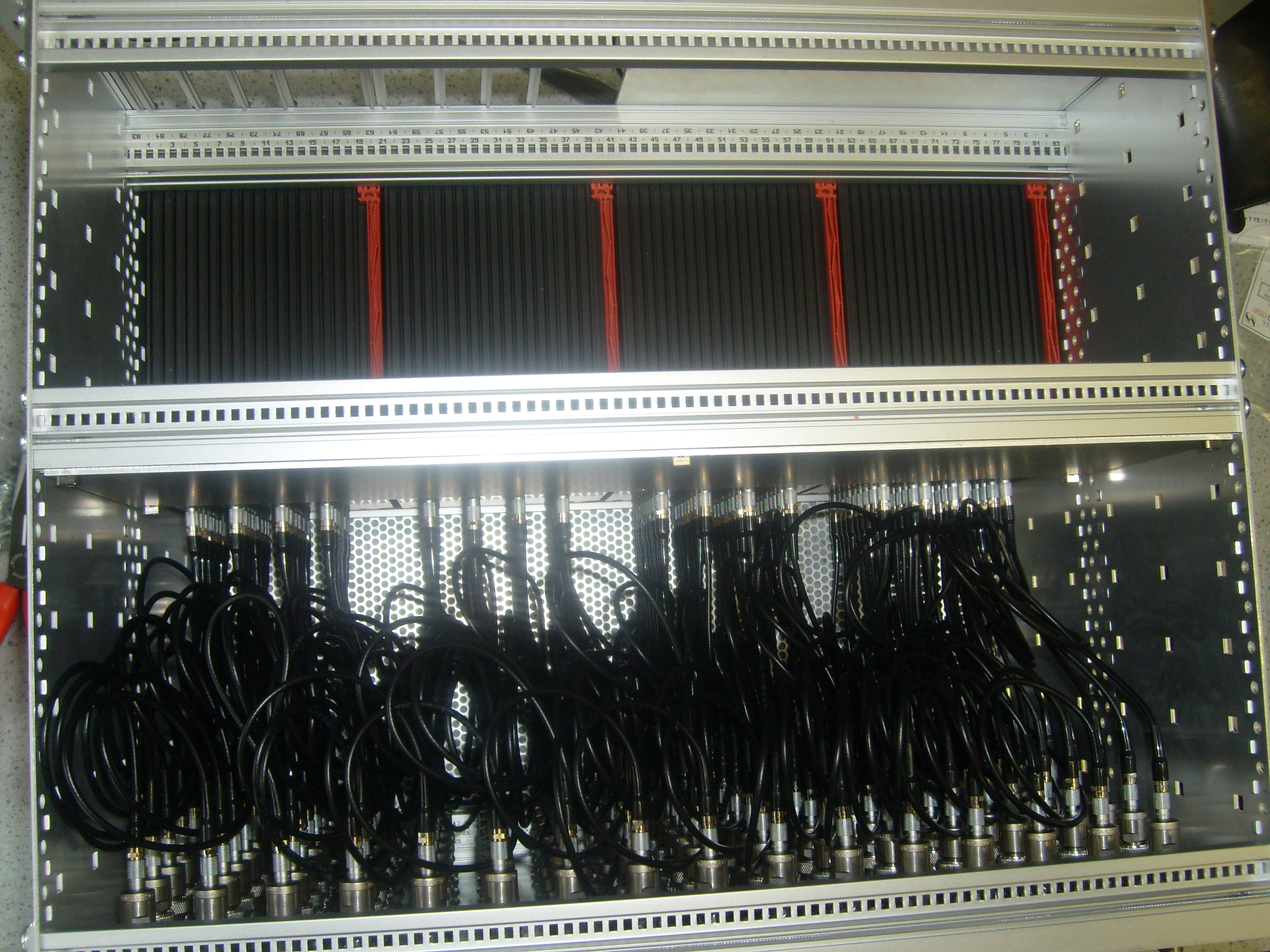 | Top view: Indroduction of backside pannell enables often change of outside connected incoming anlog signals from digitizers with 50 Ω-BNC-connectors without putting mechanical stress on backplane! |
|
☚ Back ★
projects/maps/mapsadapter/analogsignalmodul/overview.txt · Last modified: 2020/07/05 11:53 by carsten