Wiki
User Tools
Sidebar
projects:maps:mapsadapter:overview
Table of Contents
☚ Zurück ★
MAPS Adapter
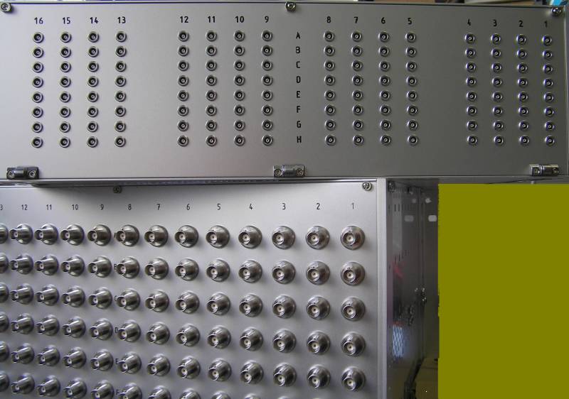
The adapter consists of one 6U crate which collects 128 BCT signals through BNC connectors at the rear panel, and one 3U “Rahmenpuls-Modul” collecting 128 gate pulses on it's rear panel.
Related topics
The adapter is a completely passive device, and is internally composed of several boards as shown below:
| Hardware | Signals and Info |
|---|---|
| Internal 6U “Analogue signal module” | |
| “68AMP_9LEMO“ These 2×8 boards bundle analogue signals and measurement gate pulses into NI-cable | Flow of "Messfenstersignal" and possible Choises there: |
| Internal 3U ”Rahmenpulsmodul” | |
| “Backplane "Rahmenpulsback"“ This board collects “Rahmenpulse” from rear side and passes them internaly to the four … | Signals to PXI-7811R FPGA board: MAPS-Bus-signals / Rahmenpulse |
| ”AMP68VG96“ These four boards adapt the “Rahmenpulse” from the backplane via VG connectors to NI-VHDCI cables connected to the NI7811 FPGA-board. | |
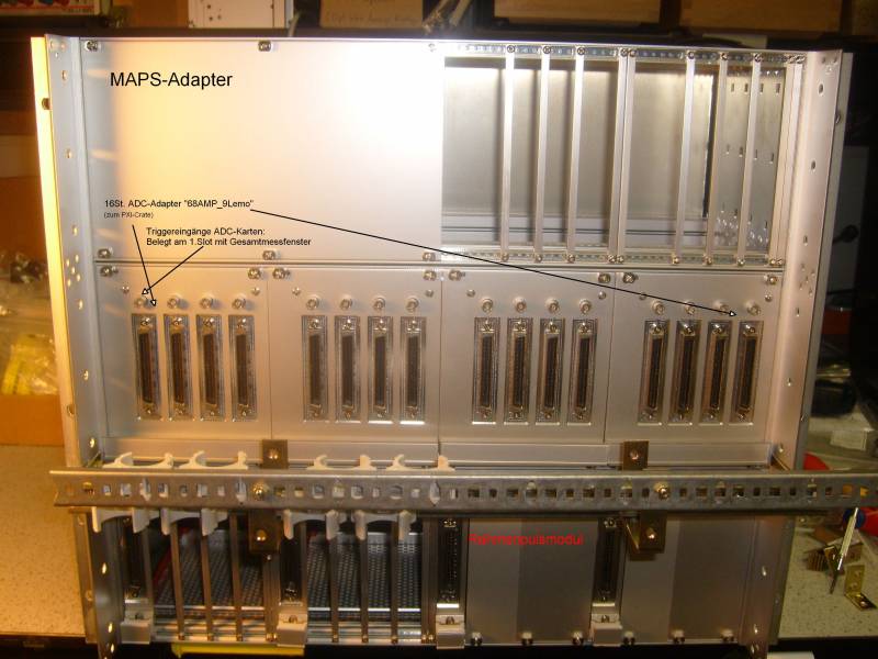
MAPS-Adapter Front View
Empty seperated slots provide storage space for the quite rigid NI multiline cables, which are available only in fixed lengths. That should provide more acurateness appart from the great number of this cables. Hole adapter interfaces between the digitizer signals analog signal and “Rahmenpuls” and the NI-crate:

MAPS-Adapter Rear View

☚ Zurück ★
projects/maps/mapsadapter/overview.txt · Last modified: 2020/07/05 12:03 by carsten
