Wiki
Sidebar
projects:maps:mapsadapter:rahmenpulsmodul:amp68vg96
Board AMP68VG96
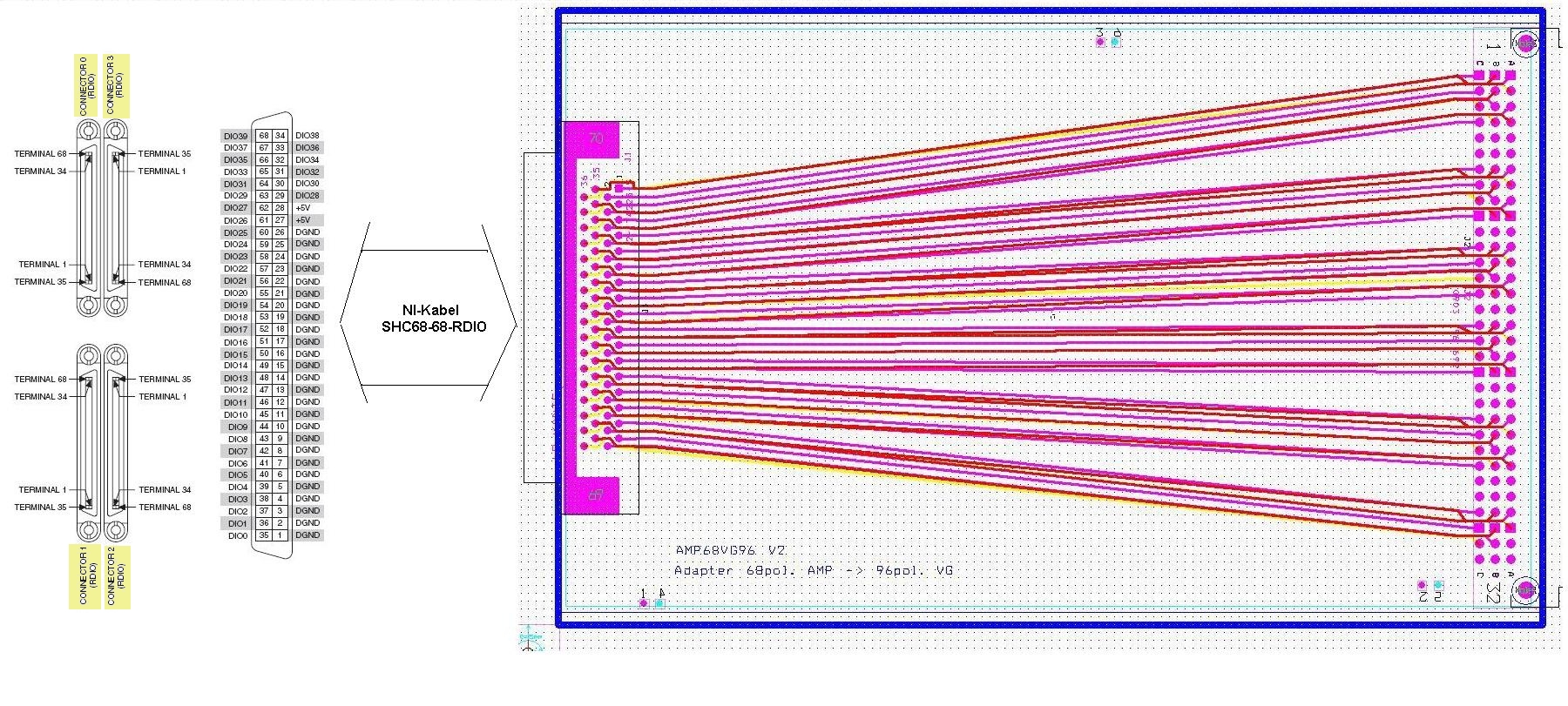
Note the counter clock wise numbering for the connectors at PXI-7811R FPGA board starting at the upper left. Following shows on board connections between VG-connector and PXI-connector in tabellaric form. Remeber: there are four connectors leaving for two different PXI-Crates (P1 or P2) and each two different connector use for “rahmenpulse (C2 or C3). This generates the four coloums in table that are to the Pin numbers (i.e P2C3 is second crate connector 3).

For those willing to do eye training here also in schematic form:
projects/maps/mapsadapter/rahmenpulsmodul/amp68vg96.txt · Last modified: 2012/01/11 14:40 by reeg