Wiki
Sidebar
instrumentss:n-dcct:overview
DC Beam Current Transformers in GSI Accelerators
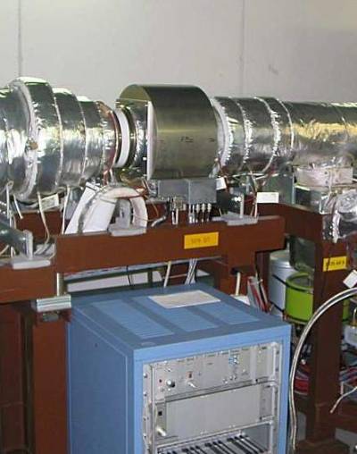
In October 1988, the first GSI-made DCCT had been installed in SIS18, Period 09
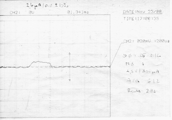
GS09DT-ML, first beam measured on Nov. 23rd 1988 (3/4 turn into F-Cup S12)
In 1992, a second GSI-DCCT was manufactured, modified according to the requirements of the ESR:
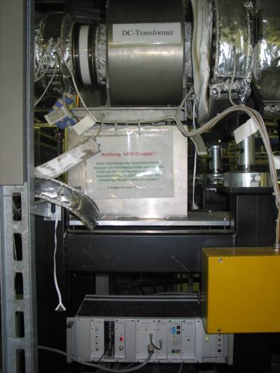
GE02DT-ML, with the associated electronics crate mounted below
As the beam intensities in UNILAC and hence in SIS18 were increased continuously over the years, the GSI-DCCT GS09DT-ML suffered from servo loop stability problems, leading to low frequency oscillations and unreliable results during the acceleration ramp. Hence, in 2006 a commercially available DCCT (Bergoz NPCT) was additionally installed in period S07:
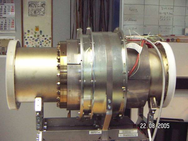
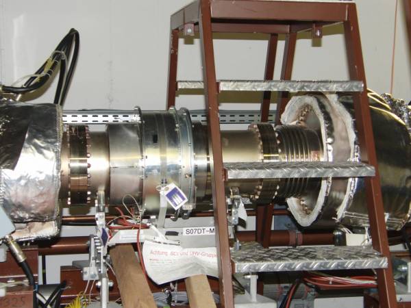
GS07DT-ML, still in lab
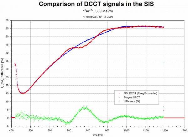
The stability problems became visible by recording the normalized output signals of both DCCTs during a typical acc. ramp, at 56mA flat top current:
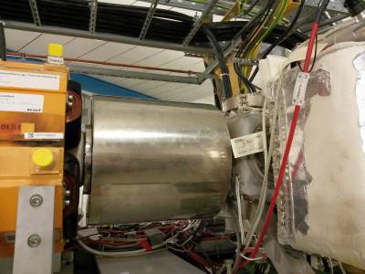
GS07DT-ML after it was moved to S01 in 2014
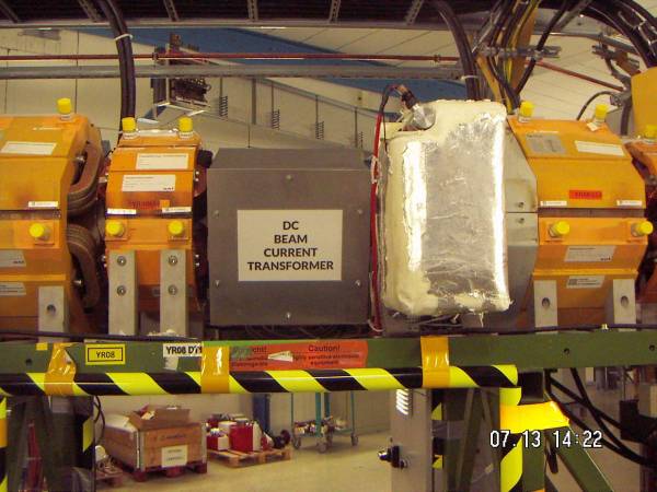
After installation, first beam tests showed a much stronger sensitivity against external magnetic fields, dominated by the dipole magnet close by:
After it was moved to period 01, further investigations showed an even stronger influence of magnetic stray fields:
The results must be taken into account for any future measures applied to data correction by hard- or software.
DC Beam Current Transformers in SIS18 and ESR - Manuals & Specifications:
GS01DT-ML Bergoz NPCT flyer
GS01DT-ML Bergoz NPCT manual
GS09DT-ML Technical Infos
GE02DT-ML Technical Infos
DC Beam Current Transformers in SIS18 and ESR - Power-Up and Adjustments:
GS09DT-ML: Adjusting of Working and Zero Points
GS09DT-ML: Power-Up & Re-commissioning
GE02DT-ML: Re-commissioning, Adjusting of Working and Zero Points
Since 2015, the old Bergoz-PCT from MSL is installed in the adapted and reconstructed Cryring:
- an electronic front end box is mounted closely to the toroid/beam tube, see below
- a 19“ half-unit electronic backend chassis is installed in the Cryring BI container
- dual-layer inner magnetic shield (μ-metal)
- single-layer outer magnetic shield (soft iron)
- single-turn induction loop wound across yoke of YR08MH for compensation of dI/&dt-induced errors → induced current is coupled into PCT toroid by single-turn winding via adjustable R
YR8DT-L, after additional soft iron shield was added
YR8DT1L, inner μ-metal (dual layer) shield visible
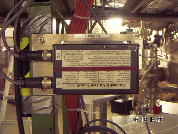
YR8DT1L, Bergoz head amplifier box (viewed from inner side of the ring)
DC Beam Current Transformer in Cryring@ESR - Manual & Specification:
YR8DT1L Bergoz PCT flyer
YR8DT1L Bergoz PCT manual
K. Unser: paper "The PCT..."
S09DT-ML DCCT Documentation
Overview documents:
dcct-s09dtml-overview1.pdf
dcct-s09dtml-overview2.pdf
dcct-s09dtml-overview3.pdf
dcct-s09dtml-overview4.pdf
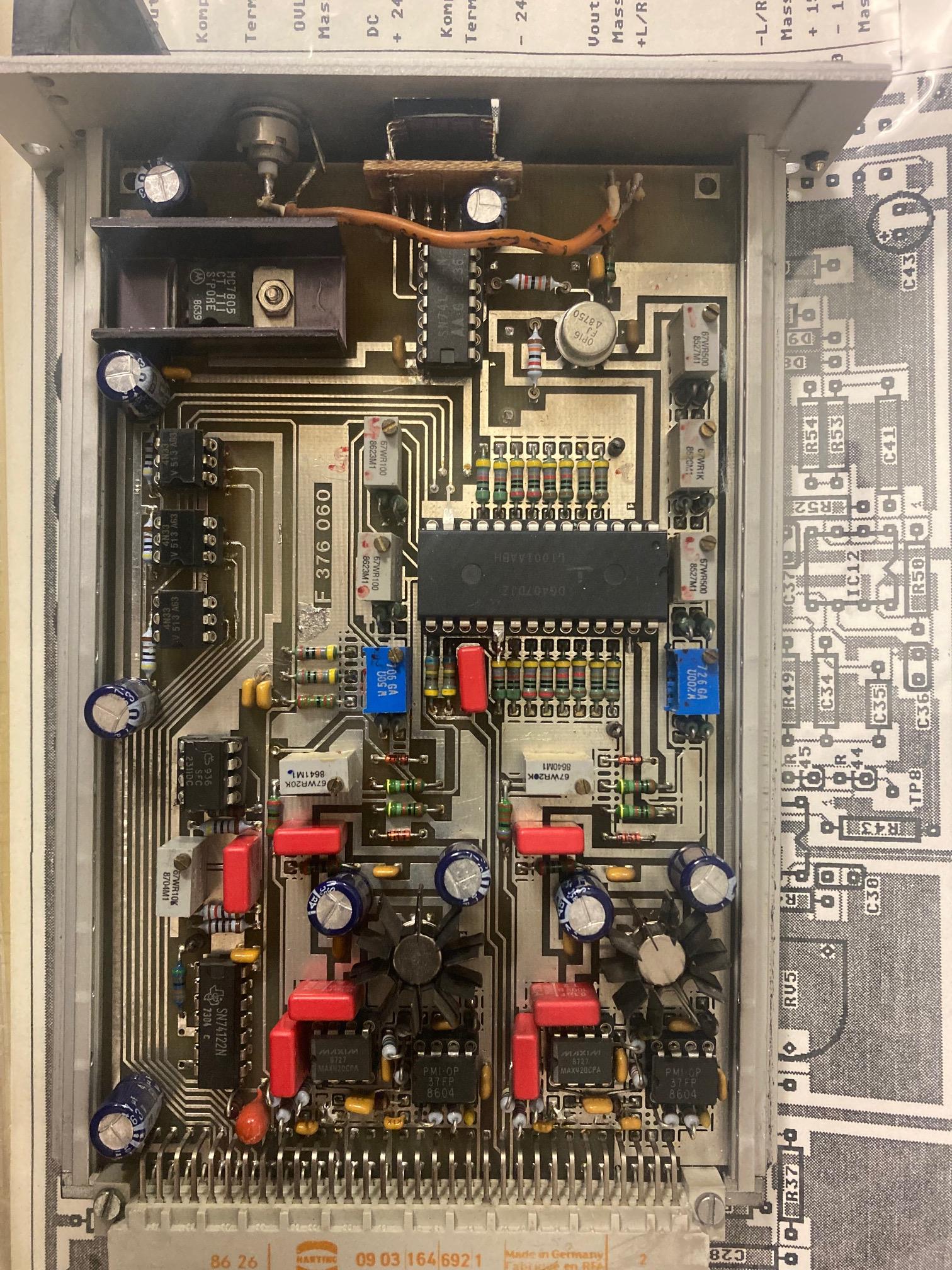
GS09DT-ML & GE02DT-ML DCCT U/F-Converter Documentation
FG444.021 Schematic and Layout: fg444.021_schaltplan_layout.pdf


Link to SdaOszi021: Analog S09 DCCT Signal
instrumentss/n-dcct/overview.txt · Last modified: 2022/11/22 12:28 by lbraisz