Wiki
Sidebar
data_acquisition_hardware
Table of Contents
CUPID Data Acquisition Hardware
At FAIR the decision for a DAQ system is based on availability on the market, costs, synergy effects, and performance. Two possible solutions for SCR DAQ are envisaged. For installations with up to two GbE camera systems the IPC as DAQ host may be used. With higher amount of channels a µTCA solution, 6 slots, is proposed. Those systems will contain an 8 channel GbE switch.
CMOS and Radiation-hardened cameras
| CMOS Camera requirements | ||
|---|---|---|
| Type | IDS uEye UI-5240SE-M-GL CMOS digital camera, monochrome |
|
| Data Interface | Gigabit Ethernet | |
| Chip size | inch | 1/8“ |
| Chip Resolution | pixel | 1280×1024 |
| Refresh rate | fps | 60 |
| Dynamic range (ADC) | 10 bit | |
| Gain (ADC) | min. 0-12 dB | |
| Integration Time | 90 µs – 20 sec | |
| Radiation-hardened Camera requirements | ||
|---|---|---|
| Type | CID video cameras (monochrome) for special installations, where high radiation hardness is necessary |
|
| Data Interface | Video Output | |
| Chip Resolution | pixel | 786 x 603 |
| Refresh rate | fps | 25 |
| Gain | 2 | |
Frame Grabber
Analog Cameras
- legacy cameras already installed
- Thermo Fischer RadHard camera (MegaRAD3)
Pleora iPort Analog-Pro External Frame Grabber
- Gbit ethernet based
- GigE Vision and GenICam compatible
Analog cameras run continuously
- rate reduction in software to 10Hz
- trigger by software
- all frames are discarded but next frame after trigger
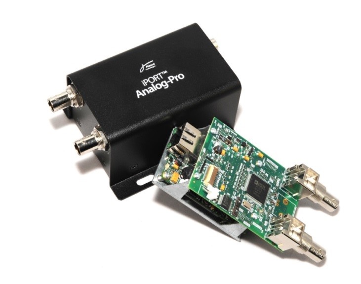
Photo of frame grabber card Pleora (Model PT01-AN1IP01-32EG).
µTCA
Attention: Configuration, issues and hardware access especially for AMC217 can be found
here.
MTCA.4 form factor 19” rack mount:
| HW Component | Type | Remarks | |
|---|---|---|---|
| µTCA System | GSI-NATIVE-R2-AM902-AC | 600W Power Supply 6-Slot MTCA.4 Chassis 2U NAT MCH | NAT and Powerbridge |
| Timing | AMC FTRN | Cosylab | |
| CPU | AM G64 | XEON | Concurrent Techn. |
| Switch | AMC217 | 8-Port Switch AMC | Vadatech |
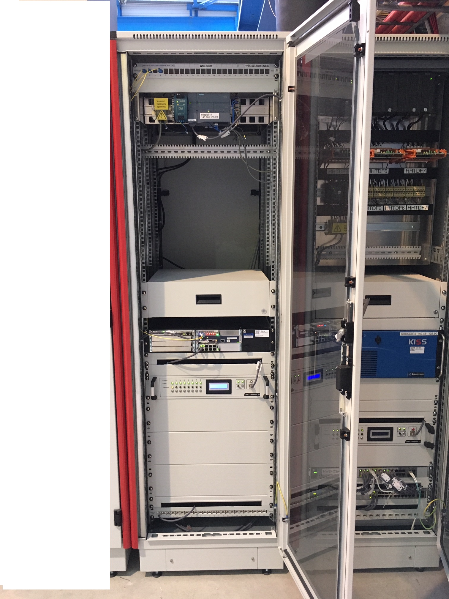
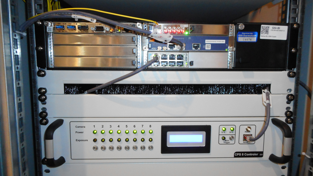
Top: Proposed MTCA.4 Chassis incl. MCH, 600W PS, CCT Core i7 or later CPU (NAT-Native-R2). Bottom: CPS 8 unit.
- Compact Modular System
- 8 Port Gbit Ethernet Switch
- multiple switches in principle possible
- Fair Timing Receiver Node
- Data Acquisition for Cameras
- via inserted 1 Gbit Ethernet Switch
- Disadvantages:
- complicated configuration of µTCA backplane ethernet lines
- suboptimal configuration:
- system worked
- 30s discovery time of cameras after camera power cycle (typical with optimal configuration: 2-3s)
Industry PC (IPC)
In case only few channels have to be read out (up to 2), a standard IPC can be used to host the GbE LAN adapter (e.g. dual port) and the FTRN. The IPC operates as standard FEC and will boot via PXEboot its OS.
| HW Component | Type | Remarks |
|---|---|---|
| Dual Port LAN Adapter | PCIe | Intel |
| Timing | Pexaria FTRN | GSI |
| IPC | Sysgen, Kontron | Core I7or better |
10 Gbit Ethernet Switch
- Data Acquisition for Cameras
- via 10 Gbit Ethernet Switch
- camera configuration
- camera readout
- via Standard LAN
- control of CPS8 controller
- Fair Timing Receiver Node
- hardware trigger (LVTTL)
- distributed via CPS8
- currently: all cameras = one trigger
- future: one camera = one trigger
Remote Control
For maintenance purposes the MTCA system can be controlled via LAN or IPMI protocol. It provides access to status, temperature, fan speed and powercycle. The system can be surveyed by the REMBRANDT system. The same type of remote operation is valid for the IPC. A remote power cycle for the cameras is feasible using the Profinet based Remote Power Control (RPC) system providing a reset pulse to the CPS8 unit.
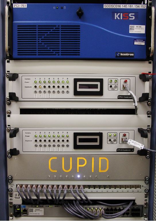
CPS8
Power supply and remote reset for up to eight digital cameras are realized by the in-house developed Camera Power Supply controller CPS8. The CPS8 is based on an Arduino single-board microcontroller and controlled via Ethernet. By sending simple ASCII commands the controlling FESA class sets the power of any attached camera. It can also obtain the power status of each connected camera. In addition, the CPS8 distributes hardware triggers to the cameras either from an external input or self-generated.
CPS8 Controller
- build in-house
- Atmel Microcontroller (Arduino) based
- simple ethernet based access
- camera power control
- camera power status
- camera trigger
- software trigger
- hardware trigger distribution
- currently: all cameras = one trigger
- future: one camera = one trigger
- burst mode
- frontpanel indicators
- camera power
- camera exposure (camera strobe output)
PLC System
A Siemens PLC PROFINET IO System (IO controller and devices) controls the aperture of each lens and LEDs to illuminate the target for calibration issues. A dedicated FESA class using the CERN SILECS library provides access to the PLC from the CUPID GUI via the ACC-Network.
The system will be set up on a 19” DIN-rail holder either close to the SCR DAQ system or in radiation-protected locations inside the tunnel. It is part of the campus PROFINET infrastructure. Plan is, to install a separate stand-alone PLC system for remote power control for all devices.
The bill of material and a schematic overview of the IO System are listed below.
| Description | Order number | Info |
|---|---|---|
| SITOP PSU200M, DC 24V/10 A | 6EP1334-3BA10 | Power supply |
| CPU 1512SP-1 PN | 6ES7512-1DK01-0AB0 | IO Controller (CPU) |
| CP 1542SP-1 | 6GK7542-6UX00-0XE0 | CP (ACC-Network) |
| IM 155-6 PN HF + Servermodul | 6ES7155-6AU00-0CN0 | IO Device (Interface) |
| BusAdapter 2xRJ45 | 6ES7193-6AR00-0AA0 | Bus Adapter |
| DQ 8x24VDC/0,5A HF | 6ES7132-6BF00-0CA0 | Digital Out - LED |
| AQ 2xU/I HF | 6ES7135-6HB00-0CA1 | Analog Out - Apertur |
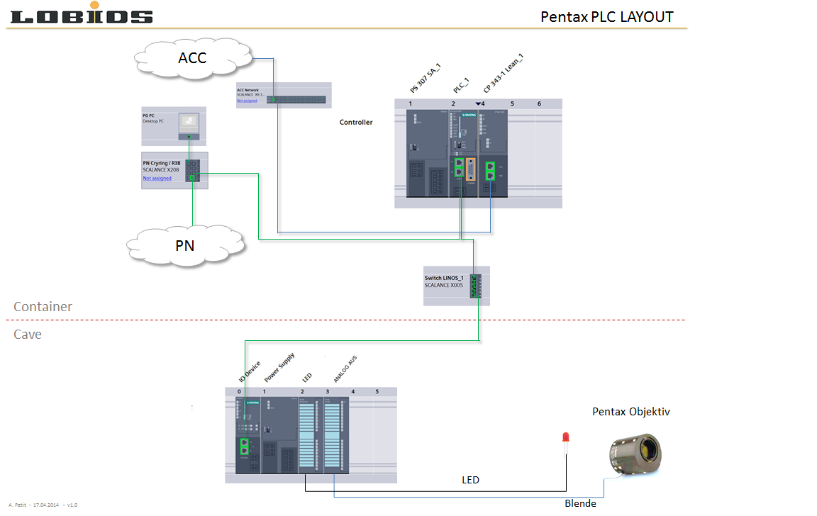
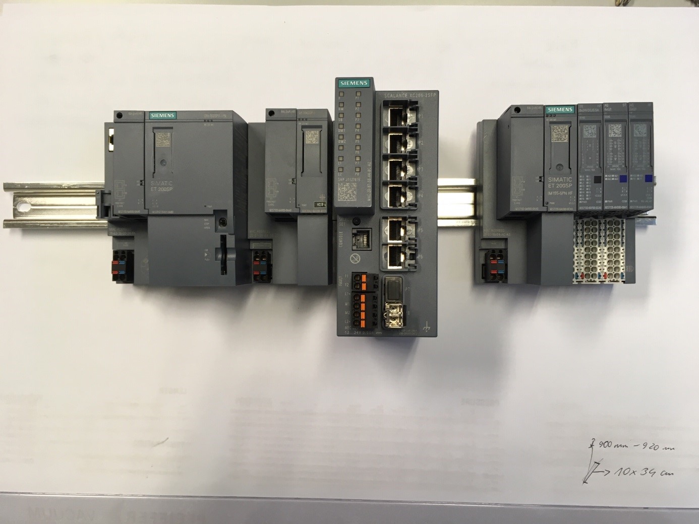
Photo of PLC system for remote-control iris and LED control.
data_acquisition_hardware.txt · Last modified: 2019/05/03 13:41 by tobiashoffmann