Wiki
User Tools
Sidebar
detector_hardware
Detector Hardware
The scintillating screen is inserted into the beam under an angle of 45°. Through a viewport, located at 90° with respect to the beam, a camera observes the screen.
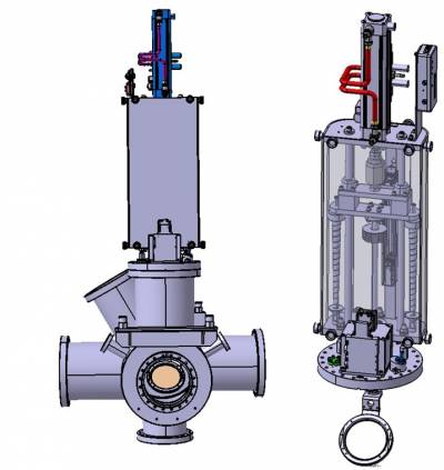
The drawing of the scintillating Screen setup on a flange with a target under 45° in respect to the beam.
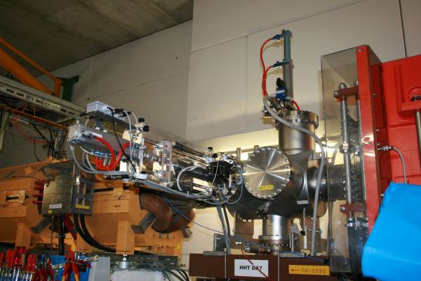
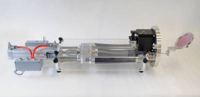
Photo of the scintillating Screen setup
The mechanical constituents of one Scintillating Screen Setup are the following parts:
- Detector consisting of scintillating screen and target holder.
- Pneumatic driven linear actuator.
- Diagnostic chamber for installation of linear actuators.
- Additional parts for detector installation on linear actuator.
Pneumatic Driven Linear Actuator
The linear actuator moves the detector (scintillating screen and holder) into the beam center and out of the beam. The four different detectors are foreseen correspond to four different linear actuators.
| Detector | Distance Flange-Beam | Stroke [mm] | Bakeout | BD-type number | Drawing number |
|---|---|---|---|---|---|
| FT-DF 2010 | 270 | 150 | No | FT-DL 2210 | BD-1018821-A-000 |
| FT-DF 2011 | 270 | 150 | Yes | FT-DL 2220 | BD-1018881-A-000 |
| FT-DF 2020 | 370 | 200 | No | FT-DL 2230 | BD-1014852-A-000 |
| FT-DF 2021 | 370 | 200 | Yes | FT-DL 2240 | BD-1018450-A-000 |
Technical drawing of linear actuator with camera setup
Photo of complete mechanical and optical system for scintillating screen.
detector_hardware.txt · Last modified: 2019/03/22 11:53 by vschaefer


