Wiki
Sidebar
instrument_hardware
This is an old revision of the document!
Table of Contents
Instrument Hardware
Detector Hardware
The scintillating screen is inserted into the beam under an angle of 45°. Through a viewport, located at 90° with respect to the beam, a camera observes the screen.
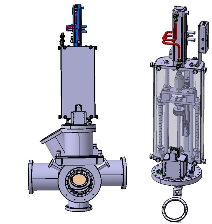
The drawing of the scintillating screen setup on a flange with a target under 45° in respect to the beam.
The mechanical constituents of one Scintillating Screen Setup are the following parts:
- Detector consisting of scintillating screen and target holder.
- Pneumatic driven linear actuator.
- Diagnostic chamber for installation of linear actuators.
- Additional parts for detector installation on linear actuator.
Pneumatic Driven Linear Actuator
The linear actuator moves the detector (scintillating screen and holder) into the beam center and out of the beam. The four different detectors are foreseen correspond to four different linear actuators.
| Detector | Distance Flange-Beam Center [mm] | Stroke [mm] | Bakeout | BD-type number | Drawing number |
|---|---|---|---|---|---|
| FT-DF 2010 | 270 | 150 | No | FT-DL 2210 | BD-1018821-A-000 |
| FT-DF 2011 | 270 | 150 | Yes | FT-DL 2220 | BD-1018881-A-000 |
| FT-DF 2020 | 370 | 200 | No | FT-DL 2230 | BD-1014852-A-000 |
| FT-DF 2021 | 370 | 200 | Yes | FT-DL 2240 | BD-1018450-A-000 |
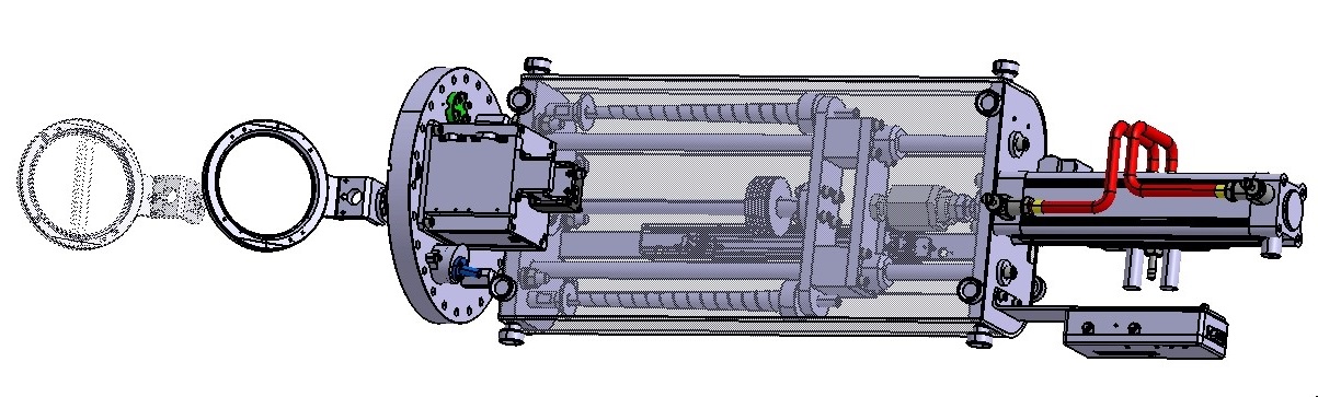
Technical drawing of linear actuator with camera setup.
Optical Setup
The optical constituents of one Scintillating Screen are the following parts:
Screen material
The detector consists of the scintillating screen (target) and the target holder. The scintillating screen is a round disk of scintillating material (solid or coated material), fixed in a holder with permanent alignment marks outside the active area.
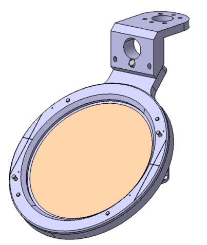
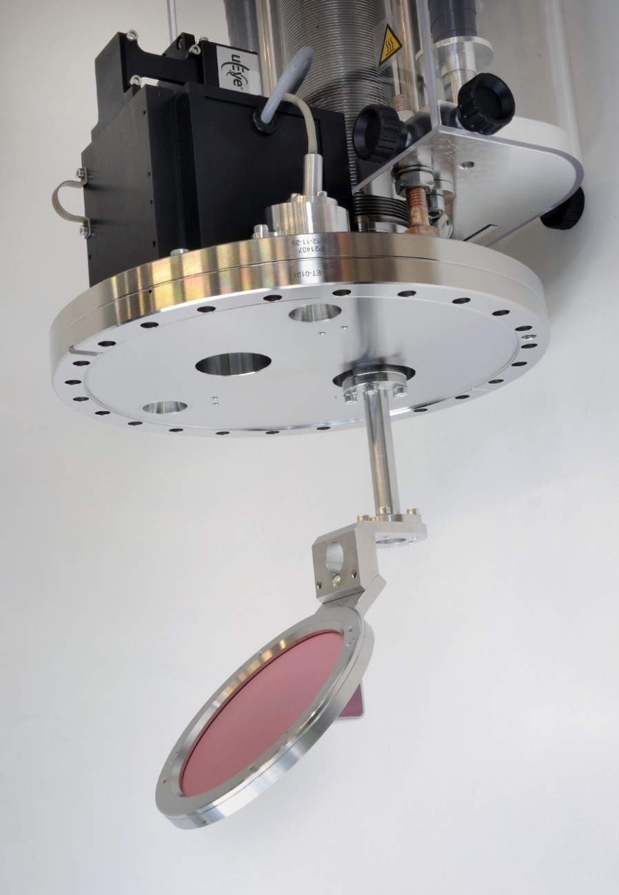
The technical drawing (left) and photo (right) of the scintillating screen on target holder.
| SCR Material | Type | Application |
|---|---|---|
| Al2O3:Cr (Chromox) | Solid target material | Standard light applications |
| Gd2O2S:Tb (P43) | Coated on a plate | Low light applications |
| YAG:Ce | Solid target material | Low light applications |
In the HEBT lines, two different detector sizes are used with an active area of Ø 100 mm and Ø 120 mm, mainly Chromox.
| Detector size (active area) | Bake-out | BD-type number | Drawing number |
|---|---|---|---|
| D100 | No | FT-DF 2010 | BD-1018552-A-000 |
| D100 | Yes | FT-DF 2011 | BD-1018926-A-000 |
| D120 | No | FT-DF 2020 | BD-1017884-A-000 |
| D120 | Yes | FT-DF-2020 | BD-1017884-A-000 |
Viewports of sufficient optical quality
For standard location CF viewport with firmly connected borosilicate window VPCF16B-L (for LED Unit) and VPCF40B-L (Camera system) from VACOM will be used. Flange from SS 1.4307 (304L) and spinning material: Kovar are used. Please keep in mind that that only annealed copper gaskets can be use.
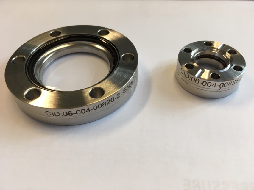
Photo of viewports for scintillating screen system.
For bakeout location CF viewport with connected borosilicate window Zero Light Glass HOVPZ16-LN for LED and HOVPZ38-LN for camera system from company Hositrad can be used. Only flange from material 316L can be use. Please keep in mind that that only annealed copper gaskets can be use.
Lens System with remote-controlled iris
The standard lens installed is the PENTAX C1614ER with fixed focal length (16mm) or PENTAX C814ER with fixed focal length (8mm), low distortion and good optical quality. A lens system with remote-controlled iris is required in order to adjust the amount of light that impinges onto the digital camera sensor. Note that the iris setting affects the depth of field. The remote control is done by setting a defined analogue input voltage as a set value for the iris opening.
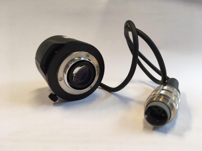
Photo of remote-controlled iris Pentax C1614ER.
Camera system
The standard camera installed is the IDS uEye UI-5240SE-M-GL, which is a digital GigE camera equipped with the radiation tested e2v CMOS sensor with 1280 by 1024 pixels. A camera internal area-of-interest limits the image to the size of the scintillating screen and reduces the amount of data transferred already in the camera. Grouped according to their location, the cameras are connected via 10 Gigabit Ethernet switch to DAQ System. The DAQ System is equipped with an additional 10 Gigabit network adapter to provide a private network for the camera readout. The PC also runs the FESA classes and provides the link via the accelerator network to the GUI. The performance of the system reached more than 15 frames per second at full resolution with one active camera and a single connected client.
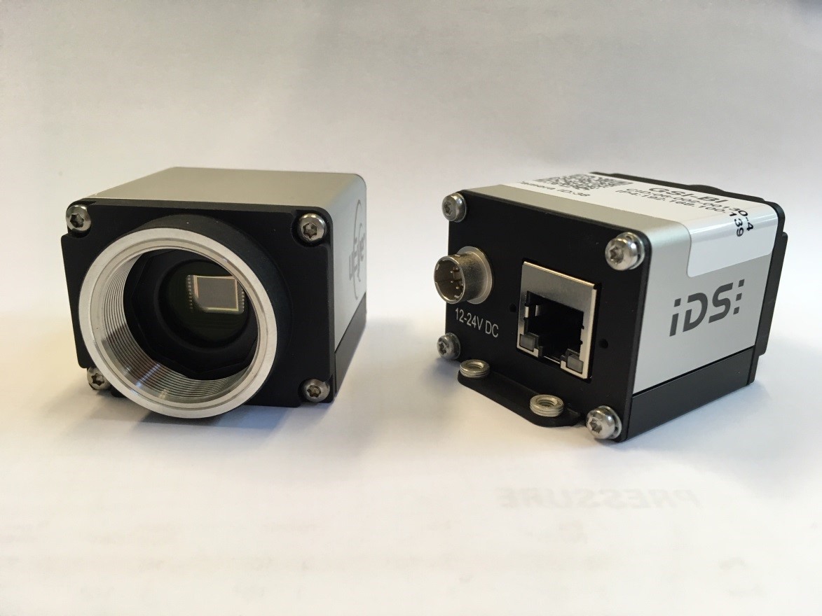
Photo of CMOS Camera IDS uEye UI-5240 SE-M-GL.
For installations, where a high radiation level is observed, a radiation-hardened solid-state CID (Charge Injection Device) based camera from Thermo Fischer Scientific, the CCIR MegaRad3 (8726DX7), will be installed. According to the manufacturer this device is tolerant to gammas, neutrons, high energy electrons and proton radiation to at least 3 MRad. Only in tests up to 14 MRad a noticeable degradation in the image quality has been reported by the manufacturer. Tests at GSI SIS18 extraction with the MegaRad3 camera have shown, that within few years of operation, no significant change in camera performance was observed.
instrument_hardware.1544108527.txt.gz · Last modified: 2018/12/06 16:02 by vschaefer