BIF:
THE BIF SYSTEM:
Beam Induced Fluorescence monitors determine the
transverse beam profiles with minimum beam disturbance.
The measurement principle is based on the excitation
of gas molecules by the passing ion beam in the beam
pipe. The emitted photons are measured by digital CCD
cameras with image intensifiers to ensure single photon
detection. Using two cameras installed above and
sideways of the beam pipe, the horizontal and vertical.
beam profiles are measured simultaneously. Currently, there are 6 BIF monitors installed in GSI accelerators and transfer lines.
PLC HARDWARE:
As PLC hardware, the SIMATIC system from Siemens
was selected. The PLC is able to set
voltages for each iris, the intensifiers and calibration
LEDs which had to be controlled manually before.
Furthermore, an easy to use remote reset capability for
supplemental hardware devices of the BIF system is
realized by relay modules. The relays support switching
of 230 volt supply voltage. Devices of the BIF system like
the cameras or the gas flow control can be restarted
remotely in case of errors.
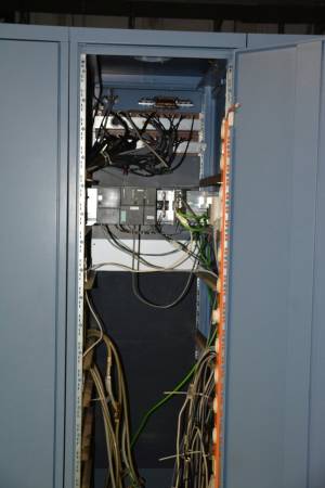
The hardware was installed at different locations along
the linear accelerator. The main controller and the Ethernet
communication module are located in an electronics
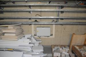
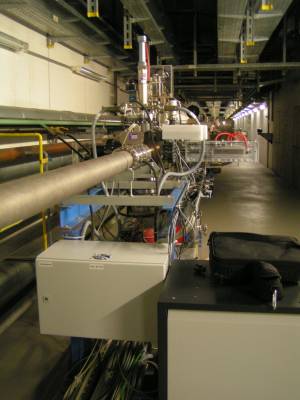
room. The distributed sub-systems with local control
units, relays and DAC devices, so-called 'satellites', are
located near the BIF hardware in a radiation safe area.
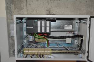
The system consists of the following Siemens
SIMATIC components:
Webinterface: SDAPLC001
CPU:
• S7-300 - the main controller
• CP343-1 Lean - for Ethernet communication
Location: LSB5, Rack15
IO-Devices: 6 in 4 Boxes:
• ET 200M - the satellite controller
• SM322 - relay with eight outputs (to control 230V power plugs)
• SM332 - 12-bit DAC with four outputs (2)
BIFUS1 BIFUS4:
Location: Unilac basement
BIFUA4 BIFUT1:
Location: Experiment basement
BIFTK2:
Location: Experiment basement
BIFTK6:
Location: Beamline TK6
pinbelegung_sps_kabel_geraet_konverter_100722.xls
analog1.xls
digital1.xls
